
The output energies of lasers have increased year-by-year since their invention. Compared to this increase of laser energies, the damage threshold of optical components has not strongly changed. Therefore, the size of optics in high-energy laser system increases. This situation could change dramatically if optics with higher damage threshold were developed. Here, we propose a high damage threshold optics using a neutral gas as an active medium. More than 95% diffraction efficiency has been achieved. The damage threshold for a 6 ns laser pulse is measured to be 1.6 kJ/cm 2 . The aperture size of the present system is about 60 mm 2 . Based on this result, we anticipate that control of a 1 kJ laser beam may be achievable using 1 cm sized optics, driven by a < 50 mJ ultraviolet laser, making this scheme promising in high power laser applications.

Since the conception of lasers, a great deal of effort has been invested in order to increase laser power and energy. High-energy lasers are opening up new research fields. These include new fusion energy sources 1 , new acceleration methods for charged particle beams 2 , and intense extreme ultraviolet (EUV) sources for semiconductor manufacturing 3 . The output energy of laser pulses has increased from 100 mJ to 2 MJ 4 during the last 50 years. Despite such rapid growth of the output energy, the damage threshold of optical elements has not increased at a similar rate. The damage threshold of dielectric coated mirrors depends on the pulse duration and laser wavelength. For the visible and near-infrared region, typical values are 1–200 J/cm 2 for a nanosecond pulse laser 5 . The damage threshold for structured optics such as a grating is lower than for flat mirrors and typical damage thresholds are 0.1–12 J/cm 2 (refs. 6,7 ). These small values are the main reason why high-energy lasers need meter-size optics.
Optical damage is a serious problem not only for energetic giant laser systems but also for high repetition rate lasers. Even well below the nominal optical damage threshold, the damage-risk is not zero. Recently, laser average power has increased significantly and laser pulse repetition rates have grown from 10 Hz to 10 kHz and more. Due to the probabilistic aspect of the optical damage, the actual useful fluence in the high repetition laser is much smaller than the singe-pulse damage limit. Once optical damage occurs in conventional solid optics, the damaged spot does not recover and it is not easy to replace the optics in a large-size optics laser system. Recently, a method for optical damage management idea has been employed, but the usable intensity is not dramatically increased. A typical reduction factor for practical use is from 2 to 10 (ref. 8 ).
This situation can be improved if transient optics are introduced. One candidate is plasma transient optics. To date, plasma gratings 9,10,11,12,13 and plasma mirrors 14 have been proposed and some are already installed in real laser systems. In general, plasma optics use the polarizability of free electrons to modulate the refractive index. Normally, these electrons are generated with nonlinear optical interactions. When a high-density plasma is created in the interaction of an intense pulse laser with a gas or solid surface, the obtainable refractive index change is around 10 −1 –10 −3 . This number is similar to the conventional optical coating. However, the energy needed to produce free electrons is typically several or tens of electronvolts per atom. This large energy deposition causes a high-energy density condition in the plasma optics and results in a short lifetime. The laser power required to produce the index modulation or change in the optics is quite large and sometimes even larger than the power of the diffracted laser beams.
To solve these problems, we propose an alternative approach to transient diffraction optics using neutral gas with a linear absorption process. The damage threshold of a gas medium for nanosecond lasers is normally >1 kJ/cm 2 (ref. 15 ), which is two orders of magnitude higher than the operating laser energy flux of conventional solid-state optics. To achieve gas-phase diffraction optics, a spatial density modulation of the gas is used. However, the typical refractive index of neutral gas is only 10 −4 or 10 −5 above unity. This low value is one of the main barriers to creating a real optical device with neutral gas medium. Some ideas to increase the optical path length were previously proposed 16 . Instead, we describe here a method to create large density modulations in a neutral gas. In this scheme, the modulation amplitude is almost 100% so that we achieve more than a half-wavelength optical path difference with 1 cm thickness of the medium. In addition, due to this large optical depth, the device can be used as a volume refractive grating to obtain asymmetric diffraction. In this case, we can concentrate the diffracted beam entirely in the 1st order diffraction with almost zero intensity for 0th and −1st order beams 17 . In this paper, we propose the transient grating made by the ozone-mixed neutral gas. It has larger 1.6 kJ/cm 2 damage threshold for 6 ns lasers and enough high (96%) diffraction efficiency.
A schematic drawing of our system is shown in Fig. 1. We use a mixed gas of ozone (O3) and oxygen (O2) at one atmosphere pressure. The ozone molecule has quite large absorption for deep ultraviolet (UV) light but almost no absorption in the visible and infrared region 18,19 . Therefore, a spatially modulated UV laser (in the following, called the UV writing beam) is used to generate an ozone density modulation. When an ozone molecule absorbs a UV photon, it dissociates into atomic oxygen (O) and an oxygen molecule (O2). At atmospheric pressure, the dissociated oxygen atom almost immediately recombines with another oxygen molecule and regenerates the ozone 20 . With this process, the initial absorbed photon energy is converted into thermal energy of O2 and O3 molecules. If we use a periodic intensity-modulated UV beam, a periodic temperature modulation is created in O3 and O2 gas with no initial density modulation. This condition leads to coupled sound and entropy waves in the gas. These waves then create the density modulation.

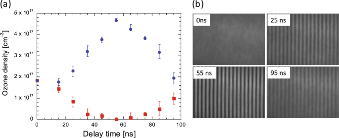
Figure 2 shows the temporal history of the ozone density profile after periodic energy deposition with the UV writing beam. In this experiment, a 100-mJ, 10-ns pulse from a 248-nm Kr*F excimer laser is used. The ozone density profile is measured by absorption measurement with 5-ns, 287-nm probe laser, and modulation of the refractive index is measured with 5 ns, and 598 nm probe. Even though the UV laser is absorbed in the ozone gas, there is no density change immediately after the UV pulse. However, the density modulation of the ozone molecules appears within 50–60 ns. The ozone density increase occurs at the destructive interference of the UV writing beam while the density decreases for constructive interference. After reaching the peak modulation, the modulation decreases and increases again. This temporal variation is a simple oscillation and the oscillation period is a function of grating fringe spacing, which is determined by the UV writing beam. The hydrodynamic motion is accurately described by hydrodynamic calculations. At the time of maximum density modulation, the induced variation of the optical path length is of the order of 1 μm. This is enough to achieve an efficient diffractive optics.
Based on the transient refractive index modulation, we have developed a diffraction optics using this medium. The diffraction efficiency is determined by the initial ozone density, the modulating Kr*F excimer laser intensity, thickness of medium, wavelength, and incident angle of the diffracted beam, and by the time interval between the UV writing beam and the diffracted beam pulse. Uniformity is also important. In this device, we use saturable absorption to produce uniform absorption along the incident UV laser. In addition, the optimum matching condition between the period of modulation, thickness, and difference of refractive index is adjusted to minimize diffraction of undesired orders and to achieve higher diffraction efficiency. After optimizing the above conditions, we could succeed to get more than 95% diffraction efficiency with this transient gas medium device.
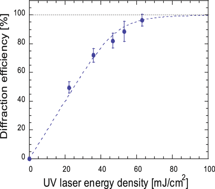
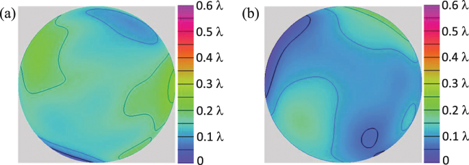
Figure 3 shows measured diffraction efficiency of this grating as a function of the UV writing beam intensity in the optimum diffraction condition. In this measurement, a 532-nm, 6-ns, 1-mJ pulse from a commercial Q-switched Nd:YAG laser is used for the diffracted laser beam. This laser has single mode in space and multi-mode in time. The typical spectrum width is about λ/Δλ = 10 4 . The density-modulated volume in this experiment is 6 mm × 10 mm × 10 mm. The diffraction efficiency is defined by the ratio of the 1st order diffraction energy to incident pulse energy. As shown in Fig. 3, the average diffraction efficiency is 96% at 63 mJ/cm 2 of the UV writing beam. We also check the fluctuation in diffraction efficiency shot by shot and single-shot standard deviation is 4.2%. The temporal window for this highest efficiency condition is about 10 ns in this grating period. We succeeded to get stable and high diffraction efficiency with low-intensity modulating laser beam energy. A two-dimensional diffraction efficiency map is shown in the Methods section. The wave front of the diffracted beams is kept within λ/10 distortion (see Methods section).
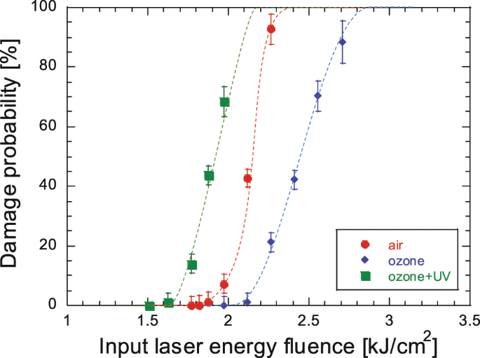
Next, we measure the damage threshold of this gas medium grating under the best diffraction condition. In nanosecond laser pulse case, the damage threshold is determined by the ionization threshold of the gas. The possible nonlinear effects in the gas are discussed in the Methods section. The occurrence of ionization damage is observed by emission from the damage point, by a change of intensity profile of the transmitted laser beam, and by detection of wave front distortion. We use 532 nm and 6 ns laser pulse to check three kinds of gases (air, and ozone-mixed oxygen gas with and without the UV laser). Figure 4 shows the percentage of damage as a function of input laser energy. The breakdown threshold of the grating medium is 1.6 kJ/cm 2 . The ozone-mixed gas has slightly lower damage threshold due to easy ionization from the excited-state atoms and molecules. Even though this damage threshold is more than two orders of magnitude higher than conventional optics. In addition, this optical element is transit optics so that the safety factor for conventional solid optical elements is no more considered.
We describe a diffraction grating in ozone–oxygen mixed gas prepared by using a UV writing beam. The diffraction efficiency is as high as 96%, the damage threshold is 1.6 kJ/cm 2 , and the diffraction control beam is 63 mJ/cm 2 . The suitability of this approach for nanosecond duration pulses has been demonstrated. For picosecond and femtosecond lasers, the damage threshold of this grating decreases due to the increased influence of nonlinear effects of the gas, but it is still expected to have several times higher damage threshold than the conventional solid grating. Extrapolating from our results acquired with a 6 × 10 mm 2 aperture and a 40-mJ Kr*F excimer laser in the linear regime, we anticipate this device may be able to control pulse energies up to 1 kJ. The fundamental function of this diffraction grating is high efficient diffraction of a high-energy flux laser beam so that many optical elements can be replaced with this grating such as optical switching, spatial mode filtering. This could lead to a large reduction in the size of high-energy laser systems.
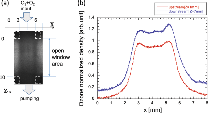
For our diffraction device, it is necessary to prepare high-density ozone-mixed gas. We use pure O2 gas (99.5%) for the ozone generation and medium of the grating, because the damage threshold of the gas medium depends on the contained micro and nano particles and the amount of aerosol 15,21,22,23 . In addition, the mixed gas must flow in a laminar way to achieve a uniform density of ozone. In our system, an atmospheric pressure discharge system is used with precooled oxygen gas (typical temperature is 10 °C). In the discharge area, a radio frequency (13 MHz) electric field (~10 kV/mm) is applied. The ozone-mixed gas flows into a flow tube whose cross section is 4–10 mm(along the laser propagation) × 10 mm(height). After 15 cm of gas-flow, at the middle of the flow tube length, we make 6 mm × 10 mm rectangular holes in two facing walls. The lasers can pass through this windowless section. From the end of the flow tube, we pump out the flow gas with a constant flow rate. The flow rate of the source O2 gas and the pumping speed of the ozone-mixed gas are adjusted to keep constant ozone density at the open window area. The typical flow speed is about 5 L/min with 10 mm × 10 mm cross section. The ozone density profile at the open window area is checked by absorption of a 287-nm probe laser. The change of the ozone density in the open window area is kept to be within a few percent as shown in Fig. 5. The ozone density is determined by the flow rate of the gas, temperature of the source gas, and discharge power. We vary the ozone fraction from 1 to 10% in this experiment to achieve the maximum diffraction efficiency. The main limitation to increase this aperture size is maintaining laminar gas flow with the windowless condition. That means the size of this optics can be increased in the direction perpendicular to the flow axes.
The ozone molecule has a large absorption cross section for deep UV photons. We use an excimer laser system (Kr*F excimer laser: wavelength of 248 nm, pulse of 15 ns, Coherent COMPEX 101) as a deep UV light source. Typical repetitive rate is from 5 to 20 Hz. The periodical intensity profile is prepared with Michelson interferometer. To make a clean high-visibility fringe pattern, the excimer laser is operated with narrow band operation with injection seeding, and the band width of the modulation writing beam is 2–3 cm −1 . The optics in the interferometer has high surface flatness. (Nominal quality is λ/20 at λ = 633 nm.) When we increase the line density, high temporal coherence of UV lasers and large angles with two UV laser beams are required to achieve sufficiently high contrast spatial modulation. In addition, the duration of the first energy deposition should be shorter than grating period divided by sound velocity, because the rise time of the density modulation is order of grating spacing divided by the sound velocity of the medium gas.
The excimer laser has relatively small saturation energy fluence, so the intensity profile at the laser oscillator exit is quite uniform. In our system, this uniform intensity profile is image-relayed onto the diffraction optics of ozone-mixed gas with a spatial filter optical system. The output energy of this laser system can be varied from 50 mJ to 200 mJ with change of operating voltage of Kr*F excimer laser. Due to the large cross section of the ozone molecule at 248 nm, the absorption is saturated. Therefore, energy deposition along the diffracting laser beam in the ozone-mixed gas is almost constant in this experiment. This uniform absorption in the entire volume of the ozone-mixed gas is a key point to achieve stable and high efficient diffraction optics.
Both the UV diffracting laser and the diffracted 0.53 μm laser are synchronized with time accuracy of a few nanoseconds in this research system. The diffracted beam is from a non-seeded Q-switched YAG laser so the actual temporal waveform of this diffracted beam has complex spike-like structure and relatively broad band spectrum (λ/Δλ ~10 4 ). Even with these non-ideal laser conditions, 96% maximum diffraction efficiency is achieved. The formation speed of the density modulation in this ozone-mixed gas grating is similar to the sound velocity of the room temperature gas. Therefore, the duration of the maximum density modulation is long enough compared to the pulse duration of the laser beams and timing accuracy in this system.
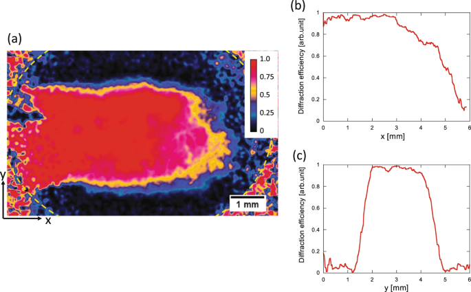
A two-dimensional map of the measured 1st order diffraction efficiency is shown in Fig. 6. In this experiment, the cross section of the diffracting beam is 4 mm × 10 mm, while the diameter of the diffracted laser beam is 10 mm. The area of the diffracted beam is indicated with dotted line in Fig. 6. The center of the UV diffracting beam is almost on the edge of this circle. As shown in this map, the diffraction efficiency at the center of the diffracting UV laser reaches almost 100%, while this number gradually decreases at the edge of the diffracting beam. This is because there is low fringe visibility of two interferometric diffracting UV laser beams with imperfect temporal coherences. Therefore, this edge reduction of the diffraction efficiency could be improved with higher temporal coherence of the diffracting UV lasers.
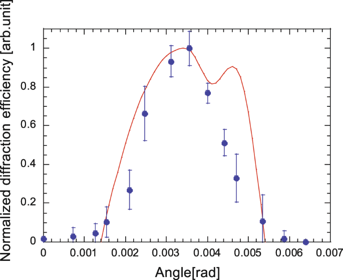
Measured angle dependence on the diffraction efficiency is shown in Fig. 7. The condition of the UV laser and the diffraction laser are the same as those of Fig. 3 experiment. The fringe spacing is about 40 μm. The 80% diffraction efficiency angle tolerance is about 0.06°. The calculated diffraction efficiency is also shown in this figure. In this calculation, step-like density modulation is assumed and the integrated phases along the tilted ray are calculated. They are in good agreement. According to the simulation, the typical bandwidth to keep high diffraction condition is as large as 1.5%. It corresponds to a 100-fs pulse-width laser.
The wave front of the 0th and 1st order diffraction beams is measured by self-referenced interferometry, in which measured beam is divided into two branches and one beam, 5× expanded, is interfered with the original one. To realize an almost perfect single spatial mode condition for the diffraction laser, output beam from a single mode fiber is used. The measured fringe is analyzed with Zernike polynomials expansion method to determine wave front distortion quantitatively. The other parameters in this experiment are the same as those in the maximum diffraction efficiency experiments.
Figure 8 shows the color counter map of the measured wave front for the 0th and the 1st order diffracted beam. It is seen that the wave front aberration of the 1st order diffraction beam is less than λ/10. Because the aberration of the 0th order beam is similar to this behavior, we conclude that there was negligible distortion of the diffracted beam in our ozone-mixed gas grating.
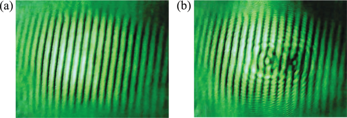
Maximum laser energy flux we can use in the ozone-mixed gas grating is as large as 1.6 kJ/cm 2 and 2.7 × 10 11 W/cm 2 . Additional wave front distortion may occur in such high energy flux condition. To learn about this effect, we measured the wave front for a case in which the diffracted 0.53 μm laser and diffracting UV laser are the same as in previous Fig. 8 experiment, and another high-intensity test laser is used for demonstration of the high-energy flux beam. A 6 ns pulse of 0.53 μm wavelength having the pulse energy from 25 mJ to 150 mJ is focused onto a 100-μm spot with a 400-mm focal length lens. This intense test beam enters into the ozone-mixed gas grating almost along the diffracted beam and with the same timing of the diffracted beams. The energy fluence of this test beam area is from 0.4 kJ/cm 2 to 2 kJ/cm 2 so that we can check both lower and higher intensity conditions of the nominal laser damage threshold (Fig. 4). As shown in Fig. 9, there is no distortion of the measured fringes when the test laser intensity is lower than the nominal optical damage threshold. However there is severe distortion in the wave front at higher intensity test beam conditions. In conclusion, there is no distortion of wave front if the laser intensity is lower than the nominal breakdown threshold.
This situation is drastically changed if the pulse duration goes to the femtosecond level. In our 30 fs experiments, self-phase modulation is lowest nonlinear effect. That threshold energy density is about 6 J/cm 2 for a wavelength of λ = 800 nm. It is also apparent that if the working gas of ozone-mixed gas was a higher damage threshold gas, such as noble gas, this threshold will be improved.
The raw experimental data are available from the corresponding authors upon reasonable request.
We would like to thank Richard. M. More for deep discussion about hydrodynamics.